|
Greg's Stuff
Images
Figures
Tables
Questions
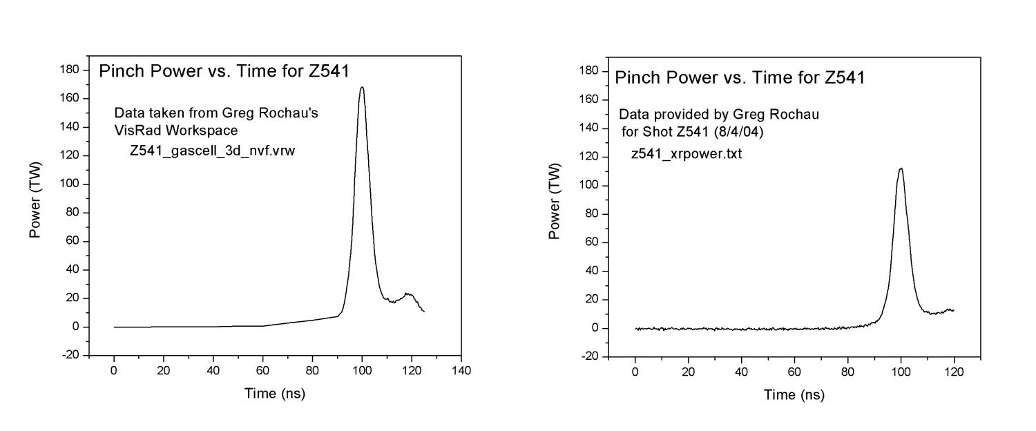
- We received from Dr. Jim Bailey the spectral data for
shot Z543. Do you have similar data which you could provide us for
shot Z541?
- Above in the Tables section is a table
containing the albedo model we used for all metal surfaces
in our workspace. Is this a good albedo model for the
metal surfaces in the simulation? Should we be using
different albedo models for different surfaces (e.g. are
the floor, current return can, etc. gold? steel?)? If so,
what albedos are appropriate for each?
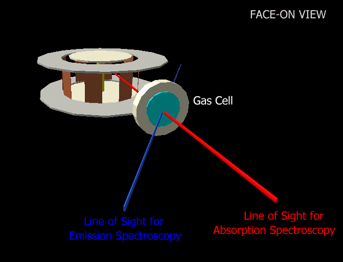
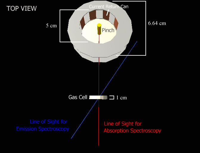
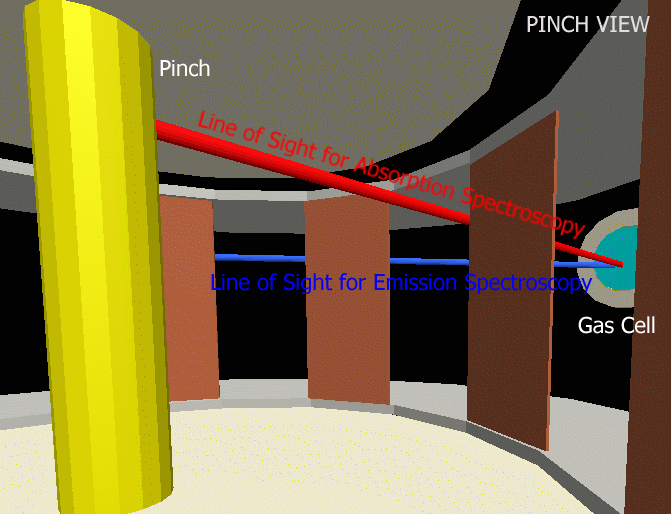
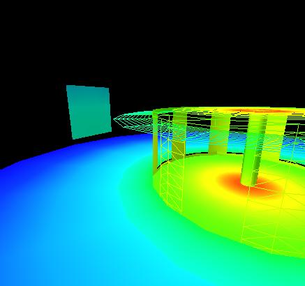
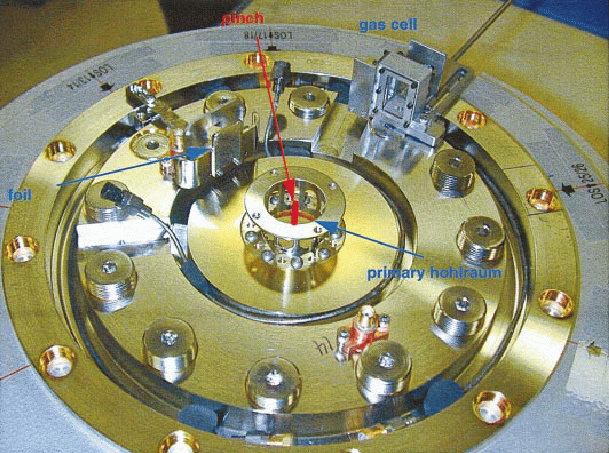
- I have also included in the Images section
schematic models of the
experimental setup, a screenshot of my VisRad
workspace, and a photo of the experimental apparatus for
these experiments given in Bailey et al. 2002.
What is the shape, dimension, and location of
the gas cell in shot Z541 and Z543?
Is there a photograph of the cell for those shots? What
are the dimensions and geometry of the current return can?
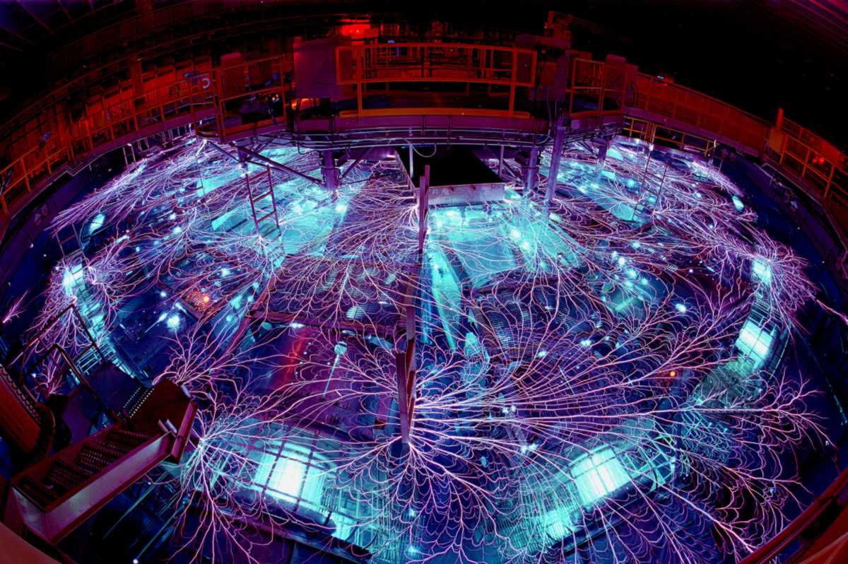
- I would like to include the well circulated photo of
the Z Accelerator which I have listed above as
zmachine.jpg, but in order to do that I need
to understand exactly what is going on in the photograph.
Here is the current caption I have for the
figure:
The Z Accelerator at Sandia
National Laboratories. Shown is an extended exposure photograph of
the banking of the Marx generator before a shot.
The accelerator tank is filled with ultra-pure water which
acts an insulator for the capacitors lining the edge of the tank.
Unfortunately, the ultra-pure water is not a perfect insulator, so
that some of the electrical energy stored in the Marx capacitors
is able to leak out into the accelerator tank and produce
the flashes of
electricity along the surface of the water known as flashover arcs
which are not unlike strokes of lighting.
Is
this description accurate, or are there other processes and/or
ideas that I should include?
- Does the current flow through the Z-pinch load in the
positive z-direction, or the negative z-direction?
|
|